Triggering the Camera
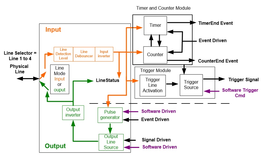
I/O Module Block Diagram
Trigger Mode Details
Genie Nano-10G image exposures are initiated by an event. The trigger event is either the camera’s programmable internal clock used in free running mode, an external input used for synchronizing exposures to external triggers, or a programmed function call message by the controlling computer. These triggering modes are described below.
-
Free running (Trigger Mode=Off): The Nano-10G free-running mode has programmable internal timers for frame rate and exposure period. Frame rate minimums, maximums, and increments supported are sensor specific. Maximum frame rates are dependent on the required exposure.
-
External trigger (Trigger Mode=On): Exposures are controlled by an external trigger signal where the specific input line is selected by the Trigger Source feature. External signals are isolated by an opto-coupler input with a time programmable debounce circuit.
Trigger features can be found in the I/O Controls category.
Trigger Source Types (Trigger Mode=On)
-
Trigger Source=Software: An exposure trigger is sent as a control command via the Ethernet network connection. Software triggers cannot be considered time accurate due to network latency and sequential command jitter. But a software trigger is more responsive than calling a single-frame acquisition since the latter must validate the acquisition parameters and modify on-board buffer allocation if the buffer size has changed since the last acquisition.
-
Trigger Source = Line 1 or 2: An external trigger signal is opto-coupled and subject to a signal debounce, input delay, plus inversion circuits.
-
Trigger Source=Timer1End Event: The Timer1 End Event is used as the internal trigger source. Refer to Counter and Timer Controls for information on those features.
-
Trigger Source=Counter1End Event: The Counter1 End Event is used as the internal trigger source.
-
Trigger Source=Timestamp Modulo Event: The Timestamp Modulo event is used as the internal trigger source.
-
Trigger Source=Action 1 or Action 2: The Action 1 or Action 2 broadcast command is used as the internal trigger source.
Input Line Details
The general purpose input line signals are connected to I/O lines 1 and 2, which have the following features for control or status indication.
-
Feature set: LineSelector (RW), LineName (RO), linePinAssociation (RO), LineFormat (RO), LineMode (RO), LineStatus (RO), LineInverter (RW), lineDetectionLevel (RO), lineDebouncingPeriod (RW).
-
Connector: See 10-Pin IO Connector Pinout for connector pinout and electrical information. The cable shell and shield should electrically connect the Genie Nano-10G chassis to computer chassis for maximum EMI protection.
-
Line Transition Validation: Each input incorporates a signal debounce circuit (following the opto-couple) to eliminate short noise transitions that could be wrongly interpreted as a valid pulse. The duration is user-programmable from 0 to 255 µs with CamExpert.
-
Line Signal Propagation & Timing: Maximum delay values are defined in Input Signals Electrical Specifications.
Trigger Overlap: Feature Details
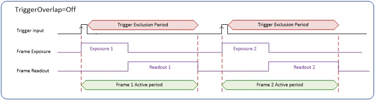
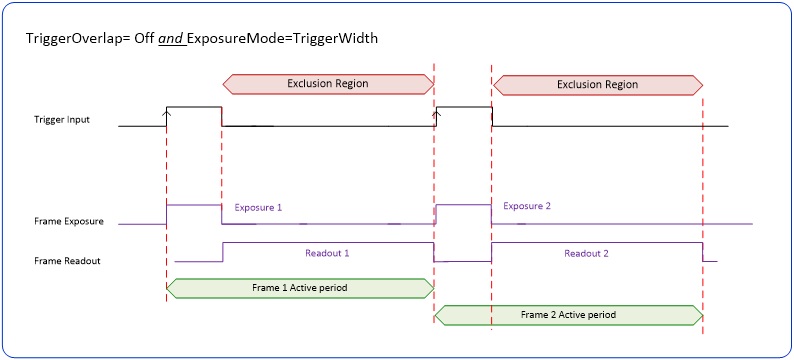
The Trigger Overlap feature defines how the Nano-10G handles triggers that might occur more frequently than the Frame Active period (an exposure plus readout period). If TriggerOverlap=Off, then triggers received before the end of the Frame Active period are ignored. Other TriggerOverlap values are dependent on the Nano-10G model.
TriggerOverlap=Off
No trigger overlap is permitted.
Diagram Conditions:
-
TriggerSelector=FrameStart (i.e., Single Frame Trigger(Start))
-
TriggerMode=On
-
ExposureMode=Timed
-
ExposureAlignment=Synchronous
-
TriggerActivation=RisingEdge
-
TriggerOverlap=Off
-
TriggerDelay=0
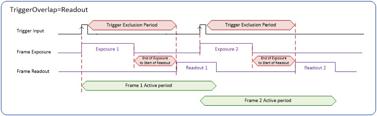
TriggerOverlap=Readout
Trigger is accepted at the beginning of the frame readout. The “End of Exposure to Start of Readout” time is sensor-dependent.
Diagram Conditions:
-
TriggerSelector=FrameStart (i.e., Single Frame Trigger(Start))
-
TriggerMode=On
-
ExposureMode=Timed
-
ExposureAlignment=Synchronous
-
TriggerActivation=RisingEdge
-
TriggerOverlap=Readout
-
TriggerDelay=0
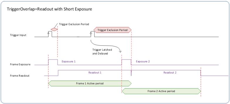
TriggerOverlap=Readout with Short Exposure
This special condition describes the case of a short exposure relative to the readout period. A trigger received before the end of the frame readout is latched and delayed until such time that the following short exposure will end with the end of the previous frame readout. The second readout period will then start immediately.
Diagram Conditions:
-
TriggerSelector=FrameStart (i.e., Single Frame Trigger(Start))
-
TriggerMode=On
-
ExposureMode=Timed
-
ExposureAlignment=Synchronous
-
TriggerActivation=RisingEdge
-
TriggerOverlap=Readout
-
TriggerDelay=0
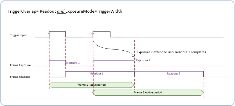
TriggerOverlap=Readout and ExposureMode=TriggerWidth
This special condition describes the case of a short TriggerWidth exposure relative to the readout period. If the next Trigger input signal occurs during the previous frame readout, attempting to stop the frame active period before the current readout is completed, the camera will continue the second exposure until the previous readout is completed. In this condition the actual exposure time is longer than the trigger input width.
Diagram Conditions:
-
TriggerSelector=FrameStart (i.e., Single Frame Trigger(Start))
-
TriggerMode=On
-
ExposureMode=TriggerWidth
-
ExposureAlignment=Synchronous
-
TriggerActivation=RisingEdge
-
TriggerOverlap=Readout
-
TriggerDelay=0
TriggerOverlap=Offand ExposureMode=TriggerWidth
Diagram Conditions:
-
TriggerSelector=FrameStart (i.e., Single Frame Trigger(Start))
-
TriggerMode=On
-
ExposureMode=TriggerWidth
-
ExposureAlignment=Synchronous
-
TriggerActivation=RisingEdge
-
TriggerOverlap=Off
-
TriggerDelay=0
Output Line Details
The general purpose output line signals are connected to I/O lines 3 and 4, which have the following features for control or status indication.
-
Feature set: outputLineSource (RW), outputLinePulseDelay (RW), outputLinePulseDuration (RW), outputLineValue (RW), outputLineSoftwareLatchControl (RW), LineSelector (RW), LineName (RO), linePinAssociation (RO), LineFormat (RO), LineMode (RO), LineStatus (RO), LineInverter (RW). See Output Signals Electrical Specifications for more information.
-
External outputs: Can be used as strobe signals to control lighting or to generate programmable pulses when specific events are generated by the camera.
-
Output on Events: Each output can be set independently to one of the available event modes defined by the outputLineSource feature.
Output High and Output Low Block Diagram
Output signal lines when either in the High or Low state are shown in the following figures with a simplified external circuit.
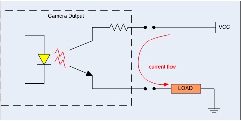
Examples of Logic HI and Logic LO output circuits
 ©
©