Precision Time Protocol Mode (IEEE1588)
PTP Mode = Precision Time Protocol
-
The PTP protocol synchronizes the Timestamp clocks of multiple devices connected via a switch on the same network, where the switch supports PTP.
-
For optimal clock synchronization the imaging network should use one Ethernet switch. Daisy-chaining multiple small switches will degrade camera clock syncs.
-
Additionally, the Ethernet switch connecting cameras to the imaging network should implement “PTP Boundary Clock” hardware.
-
To use a multi-port NIC adapter or computer with multiple NIC ports instead of a switch, that multiport NIC must be capable to be configured as the common Master PTP source for all its networks. Such a configuration requires using the multi-port NIC’s configuration software.
-
Genie Nano-10G cameras can automatically organize themselves into a master-slave hierarchy, or the user application configures a camera master with n-number of slaves. The auto-configuration process typically happens within 2 seconds.
-
The automatic organizing procedure is composed of steps (as defined by IEEE 1588) to identify the best clock source to act as master. When only Nano-10G cameras are used, since they are equal, the last selection step is to identify the Nano-10G with lowest value MAC address to be the clock master.
-
The feature TimeStamp Source is automatically changed to IEEE1588 when PTP Mode is enabled. This timestamp tick (in ns) cannot be reset by the user.
-
The Genie Nano-10G cameras implement additional features designed to synchronize multiple camera acquisitions via IEEE 1588 (PTP Mode) – not via external camera trigger signals.
PTP Master Clock Identity
The clock ID of the current best master is an Extended Unique Identifier (EUI)-64 “64-bit ID”, converted from the 48-bit MAC address, by inserting 0xfffe at the middle of the MAC address.
-
The standard MAC address in human-friendly form is six groups of two hexadecimal digits as this example shows (excluding spaces): “0a 1b 2c 3d 4e 5f”
-
The Extended Unique Identifier format is (excluding spaces): “0a 1b 2c fffe 3d 4e 5f”
An Example with two Nano-10G Cameras
The following basic steps configure two Nano-10G cameras connected to one computer via an Ethernet switch, configured with two instances of CamExpert, to grab a frame every second, controlled by a modulo event via PTP.
For each camera set features as follows:
I/O Controls — select Trigger Mode=ON, Tigger Source=Timestamp Modulo Event
Event Controls — select PTP Mode=Automatic
-
Note how one Nano-10G automatically becomes Master while the other becomes Slave
Event Controls — to have a modulo event every second, set Timestamp Modulo Event=1000000000
Click Grab on each instance of CamExpert. With the two cameras aimed at the same moving object, you see that each camera grabs a frame at the same time.
IEEE 1588 Reference Resources
For additional information: http://standards.ieee.org
PTP Standard Reference: IEEE Std 1588-2008 — IEEE Standard for a Precision Clock Synchronization Protocol for Networked Measurement and Control Systems
Examples using Timestamp Modulo Event for Acquisitions
The Timestamp Modulo event is used to synchronize multiple camera acquisitions and automate repetitive acquisitions based on either the camera’s internal Timestamp counter or a system wide PTP counter. The Nano-10G internal Timestamp clock has a 1μs tic, while the PTP clock has 8 nanosecond tics (PTP: IEEE1588–Precise Time Protocol).
Both Timestamp counters increment continuously but can be reset to zero with ‘timestampControlReset’ if ‘ptpMode=Off’, else only the internal camera Timestamp counter resets.
Case Examples Overview
The following case examples use a simplified Timestamp timeline, which for clarity is shown with time tics from 00 to 60 without units. A timeline scale based on real time is not required to describe the usage concepts. These examples also apply equally to using an internal Timestamp clock or a system PTP clock.
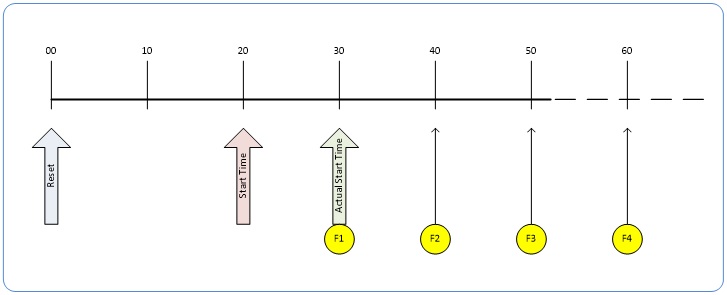
Case 1: Simple Repeating Acquisitions as Upcoming Events
Conditions:
-
initial timestampControlReset resets Timestamp counter
-
timestampModuloStartTime at 20
-
timestampModulo = 10
-
timestampModuloActualStartTime = First Event generated (F1)
After the Timestamp Reset, the first acquisition is made when the Modulo reaches the +10 tick Timestamp count, following the programmed start time. Acquisitions repeat at every +10 Timestamp tick until stopped.
Case 2: Potential Uncertainness to the Start Time
Conditions:
-
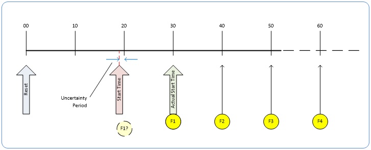
initial timestampControlReset resets Timestamp counter
-
timestampModuloStartTime at < 20
-
timestampModulo = 10
-
timestampModuloActualStartTime = first event (F1)
Case 2 differs only from case 1 by showing that there is a period of uncertainty if the start time is too close to the first modulo count that follows. The first frame acquisition may occur at the first modulo count time or at the following. The actual value for the uncertainty period may vary with different camera and network conditions.
Case 3: Timer Reset Before the Actual Start Time
Conditions:
-
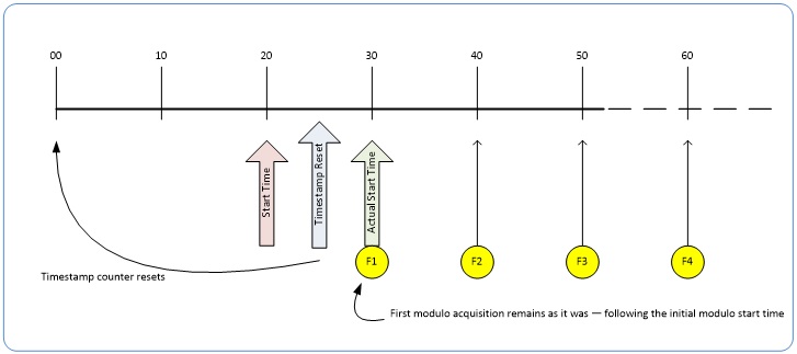
initial timestampControlReset resets Timestamp counter
-
timestampModuloStartTime at 20
-
timestampModulo = 10
-
second timestampControlReset at count 25
-
timestampModuloActualStartTime = first event (F1)
After the initial Timestamp Reset which starts the Timestamp counter, the Modulo start time is at 20. The Modulo 10 actual start time for the first acquisition is at Timestamp 30 (as described in Case 1).
Now if a new Timestamp reset happens between the Start Time and acquisition Actual Start Time, the Timestamp counter will restart from time 00, but the Start Time value has already been stored, thus the modulo Actual Start Time remains at 30. In this condition the Actual Start Time did not reset as might be expected.
Case 4: Timer Reset After the Actual Start Time
Conditions:
-
initial timestampControlReset resets Timestamp counter
-
timestampModuloStartTime at 20
-
timestampModulo = 10
-
timestampModuloActualStartTime = first event (F1)
-
second timestampControlReset at 35
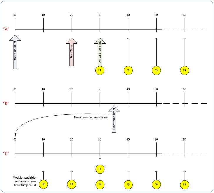
This case describes the Modulo process if there is a Timestamp counter reset after a modulo controlled acquisition occurs.
-
“A” shows the initial conditions with the first acquisition (F1) at the actual start time.
-
“B” shows a Timestamp reset occurring after the first acquisition.
-
“C” shows that acquisitions then continue at the first modulo 10 time after the reset due to acquisitions already in progress compared to the example case 3 above.
Case 5: Changing timestampModulo During Acquisitions
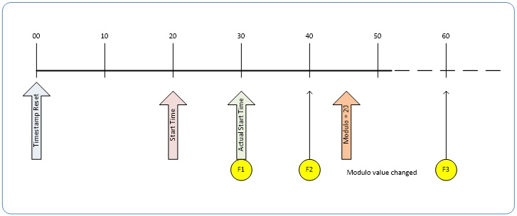
Conditions:
-
initial timestampControlReset resets Timestamp counter
-
timestampModuloStartTime at 20
-
timestampModulo = 10
-
timestampModuloActualStartTime = first event (F1)
-
timestampModulo changes to 20
Case 5 shows that the Modulo value can be changed dynamically. Using the simple example of case 1, after the second acquisition (F2) the Modulo value is changed from 10 to 20. The third acquisition now occurs at modulo 20 time following the previous acquisition.
 ©
©