Lens and Optics
Choosing a Lens with the Correct Image Circle
Each Nano-10G model requires a lens with an image circle specification to fully illuminate the sensor. The following section graphically shows the minimum lens image circle for each Nano-10G model family along with alternative lens types. Brief information on other lens parameters to consider follows those sections.
Lens Options for Models 6200 and 8200
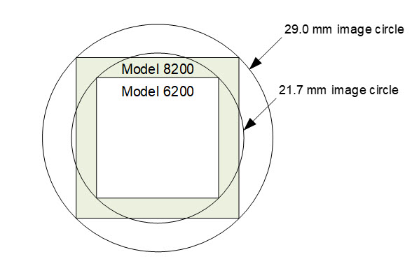
The following figure shows the lens image circle relative to the Genie Nano-10G models that use the Emerald 37M and Emerald 67M sensors. Cameras with an M42 screw mount need an image circle exceeding the diameter of the sensor.
M8200 and C8200 models are APS-C format; M6200 and C6200 models are 1.4” format.
Additional Lens Parameters (Application Specific)
There are other lens parameters that are chosen to meet the needs of the vision application. These parameters are independent of the Nano-10G model (assuming that the Lens Mount and Lens Sensor Size parameters are correct, as previously covered in this section). Consult with a vision system integrator or lens specialist when choosing lenses since there is a trade-off between the best lenses and cost. An abridged list of lens parameters follows – all of which need to be matched to the application.
-
Focal Length: Defines the focus point of light from infinity. This parameter is related to the Nano-10G mount (C mount). See Back Focal Distance in theCommon Specifications table.
-
Field of View: A lens is designed to image objects at some limited distance range, at some positive or negative magnification. This defines the field of view.
-
F-Number (aperture): The lens aperture defines the amount of light that can pass. Lenses may have fixed or variable apertures. Additionally, the lens aperture affects Depth of Field which defines the distance range which is in focus when the lens is focused at some specific distance.
-
Image Resolution and Distortion: A general definition of image quality. A lens with poor resolution seems to never be in focus when used to image fine details.
-
Aberrations (defect, chromatic, spherical): Aberrations are specific types of lens faults affecting resolution and distortion. Lens surface defects or glass faults distort all light or specific colors. Aberrations are typically more visible when imaging fine details.
-
Spatial Distortions: Describes non-linear lens distortions across the field of view. Such distortion limits the accuracy of measurements made with that lens.
Optical Considerations
This section provides an overview to illumination, light sources, filters, lens modeling, and lens magnification. Each of these components contribute to the successful design of an imaging solution.
Illumination
The amount and wavelengths of light required to capture useful images depend on the application. Factors include the nature, speed, and spectral characteristics of objects being imaged, exposure times, light source characteristics, environmental and acquisition system specifics, and more. The Teledyne DALSA Web site provides information on this potentially complicated issue (Learn > Knowledge Center or Application Notes). Review the sections of interest.
It is often more important to consider exposure than illumination. The total amount of energy (which is related to the total number of photons reaching the sensor) is more important than the rate at which it arrives. For example, 5 mJ/cm2 can be achieved by exposing 5 mW/cm2 for 1 ms or exposing 5 W/cm2 for 1 ms.
Light Sources
Keep these guidelines in mind when selecting and setting up light source:
-
LED light sources are relatively inexpensive, provide a uniform field, and longer life span compared to other light sources. However, they also require a camera with excellent sensitivity.
-
Halogen light sources generally provide very little blue relative to infrared light (IR).
-
Fiber-optic light distribution systems generally transmit very little blue relative to IR.
-
Some light sources age such that over their life span they produce less light. This aging may not be uniform—a light source may produce progressively less light in some areas of the spectrum but not others.
IR Cut-off Filters
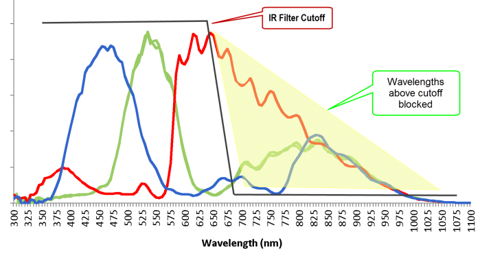
Genie Nano-10G color cameras have a spectral response that extends into near IR wavelengths (as defined for each sensor model in the sensor specification descriptions). Images captured will have washed out color if the sensor response is not limited to the visible light band. To prevent infrared from distorting the color balance of visible light acquisitions, use a “hot mirror” or IR cut-off filter that transmits visible wavelengths but does not transmit near infrared wavelengths and above.
Guidelines for Choosing IR Cut-off Filters
The following graphic, using a color sensor response spectrum, shows the transmission response of typical filters designed for CMOS sensor cameras. When selecting an IR cut-off filter, choose a near infrared blocking specification of ~650 nm. Filters that block at 700 nm or longer wavelengths, designed for CCD cameras, are not recommended for Genie Nano-10G color cameras.
For Nano-10G models, contact Midwest Optical for available IR cut filter fitting the M42 x 1 mm thread (example part: M42x1C).
Midwest Optical Systems, Inc.
Office: 847-359-3550
Fax: 847-359-3567
https://midopt.com/
Back Focal Variance when using any Filter
Inserting a filter between a lens and sensor changes the back focal point of the lens used. A variable focus lens simply needs to be adjusted, but in the case of a fixed focus lens, the changed focal point needs correction.
The following simplified illustration describes this but omits any discussion of the Optics, Physics, and the math behind the refraction of light through glass filter media.
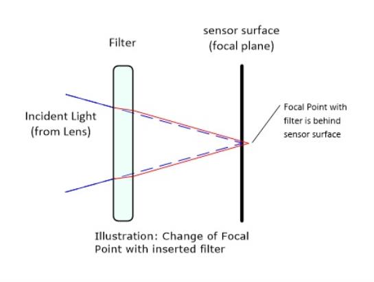
In this example, when a glass filter is inserted between the lens and the camera sensor, the focal point is now about 1/3 of the filter thickness behind the sensor plane.
When a 1 mm thick filter is used with a fixed focus lens, a 1/3 mm C‑mount shim (spacer) is required to move the lens focal point back to the sensor surface. Such shims are available from filter and lens suppliers. Alternatively, use a variable focus lens and secure its focus ring after adjustment.
For users interested in installing their own choice of filters, please refer to application note:
G3-AN0001 – Installing Custom Optical Filters into Genie Nano available here https://www.teledynedalsa.com/en/support/documentation/app-notes/
Lens Modeling
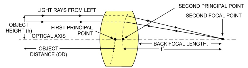
Any lens surrounded by air can be modeled for camera purposes using three primary points: the first and second principal points and the second focal point. The primary points for a lens should be available from the lens data sheet or from the lens manufacturer. Primed quantities denote characteristics of the image side of the lens. That is, h is the object height and h¢ is the image height.
The focal point is the point at which the image of an infinitely distant object is brought to focus. The effective focal length (f¢) is the distance from the second principal point to the second focal point. The back focal length (BFL) is the distance from the image side of the lens surface to the second focal point. The object distance (OD) is the distance from the first principal point to the object.
Primary Points in a Lens System
Magnification and Resolution
The magnification of a lens is the ratio of the image size to the object size:
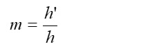
Where m is the magnification, h’ is the image height (pixel size) and h is the object height (desired object resolution size).
By similar triangles, the magnification is alternatively given by:
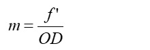
These equations can be combined to give their most useful form:
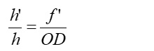
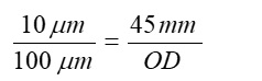
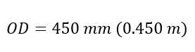
Example: An acquisition system has a 512 x 512 element, 10 µm pixel pitch area scan camera, a lens with an effective focal length of 45 mm, and requires that 100 µm in the object space correspond to each pixel in the image sensor. Using the preceding equation, the object distance must be 450 mm (0.450 m).
 ©
©